FLAT 30 % OFF Apply Coupon Code GET30
AutoCAD is Very Powerful drafting CAD software used to create 2D Drawings and 3D Models Precisely
Training Higlights
Live Training
Doubts Session
Lifetime Recording
Free Ebook
Interview Calls
ISO Certificate
Course Syllabus
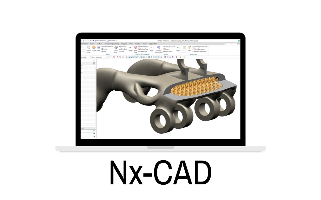
Introduction to CADDESK, Mechanical CAD/CAM/CAE Software, Basic Layout NXCAD and its uses,Advantages.
Interface of NX CAD,Mouse function, Basic commands (Save, Open, Import, Export.)
Sketch (Sketching, sketch in task environment, sketch curve) Sketch (Constraint, Dimensions)
Design feature (Extrude, Revolve, datum plane, datum axis, datum CSYS, datum point.)
Block, Cylinder, Cone, Sphere, hole, boss, pocket) (Pad,Emboss, Slot, Groove, rib, draft, thread)
Pattern feature, mirror feature, unite, subtract, intersect, sew, un-sew, join face)
Design feature (Trim body, split body, trim sheet,extend sheet, un-trim,divide face, delete edge, delete bodyDesign feature (shell,thicken, scale, offset, draft, chamfer, edge blend, face blend) Drafting (Introduction, View creation wizard, base view, update view, section view) (Annotations, dimensions, tables.) (custom symbol, drawing format)
- ASSEMBLY MODELING-I
- The Assembly Environment
- Invoking the Assembly Environment
- Invoking the Assembly Environment Using the Assembly
- Template from the New Dialog Box
- Invoking the Assembly Environment in the Current Part File
- Types of Assembly Design Approaches
- Creating Bottom-up Assemblies
- Placing Components in the Assembly Environment
- Changing the Reference Set of a Component
- Applying Assembly Constraints to Components
- Points to Remember while Assembling Components
- Creating a Component Array in an Assembly
- Replacing a Component in an Assembly
- Moving a Component in an Assembly
- Repositioning a Component in an Assembly
- Mirroring a Component in an Assembly
- Modifying a Component in the Assembly File
- ASSEMBLY MODELING-II
- The Top-down Assembly Design Approach
- Creating Components Using the Top-down Assembly Design Approach
- Creating Subassemblies
- Editing Assembly Constraints
- Modifying the Assembly Constraints
- Checking the Interference between the Components of an Assembly
- Checking Interference and Clearance
- Using the Check Clearance Analysis
- Checking Interference Using the Assembly Clearance Method
- Checking Interference and Clearance, and Analyzing
- Cross-sections of Components Using the View Section Tool
- Creating Exploded Views of an Assembly
- Exploding Views Automatically
Exploding Views Manually
- SURFACE MODELING
- Introduction to Surface Modeling
- Invoking the Sheet Modeling Environment
- Creating an Extruded Surface
- Creating a Revolved Surface
- Creating a Ruled Surface
- Creating a Surface Using the Through Curves Tool
- Creating a Surface Using the Through Curve Mesh Tool
- Creating a Surface Using the Four Point Surface Tool
- Creating a Swoop Surface
- Creating the Planar Surfaces from 2D Sketches and
- Edges of Solid or Surface
- Creating a Transition Surface Using the Transition Tool
- Creating an N-Sided Surface
- Creating a Silhouette Flange Surface
- Extending a Surface Using the Law Extension Tool
- Creating a Surface Offset Using the Offset Surface Tool
- Trimming and Extending a Surface Using the Trim and Extend Tool
- Trimming a Sheet by Using the Trimmed Sheet Tool
- Creating a Surface Using the Studio Surface Tool
- Creating a Surface between Two Walls Using the Styled Blend Tool
- Creating Surfaces Using the Styled Sweep Tool
- Sewing Individual Surfaces into a Single Surface
- Adding Thickness to a Surface
- ADVANCED SURFACE MODELING
- Creating Curves from Bodies
- Creating Intersection Curves
- Creating Section Curves
- Creating Extract Curves
- Advanced Surface Modeling Tools
- Creating Dart Features
- Creating Emboss Sheet Features
- Creating Face Blend Features
- Creating Soft Blend Features
- Creating Fillet Features
- Creating Bridge Features
- SHEET METAL MODELING
- Customer defaults,
- Tabs,
- Base features,
- Secondary features,
- Flanges, full width flange,
- Centered flange, at end flange,
- Offset flange, contour,
- Contour flange, lofted flange,
- Corner,
- Break corner,
- Closed corner,
- Three bend corner,
- Job, bend, unbend,
- Dimple,
- Louver, cutout, bead, solid punch,
- Edge rip, flat solid,
- Advanced sheet metal features.
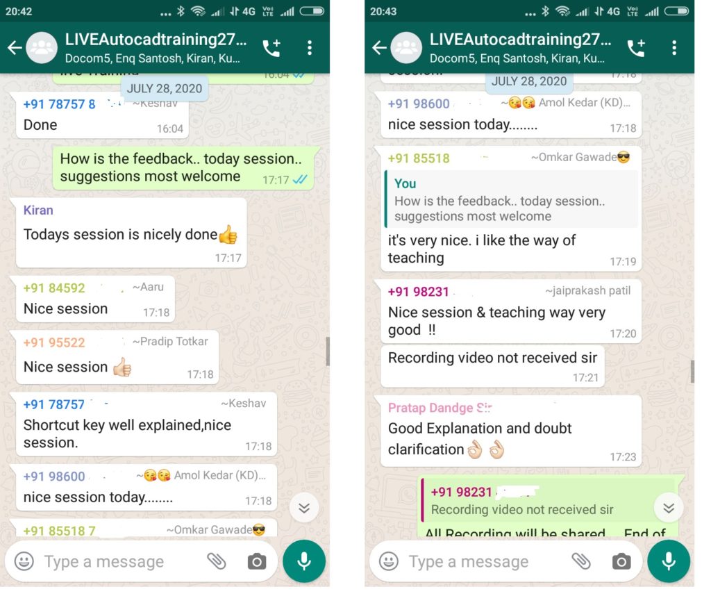
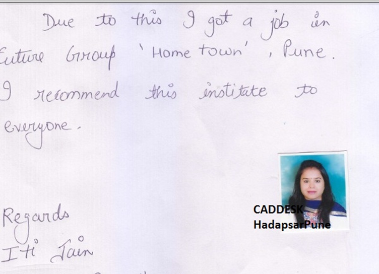
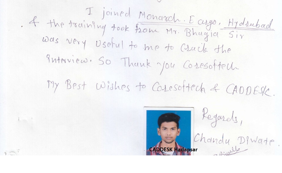
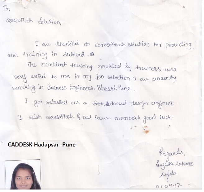
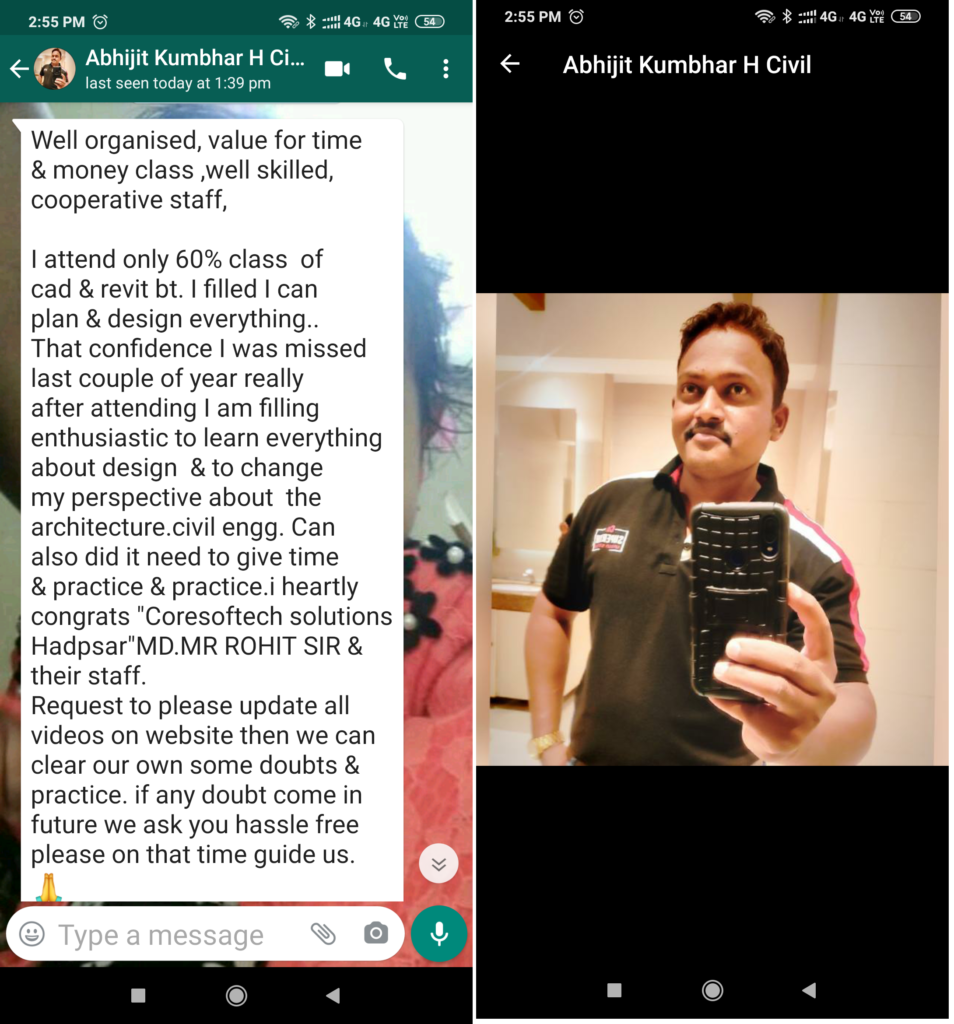
Feed Back - What our Student Says
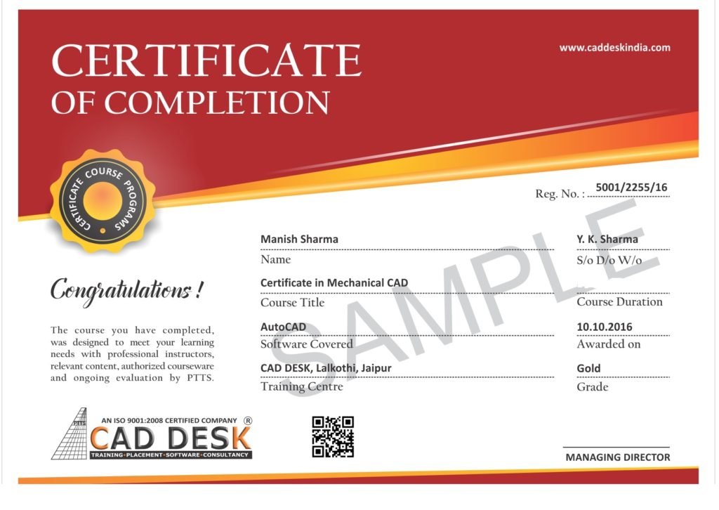
How will you get your certificate?
After Successful Completion Course Students will get ISO Certified SoftCopy via Mails or Can be Easily Downloaded from https://caddeskpune.com
Assistance with all Leading Certification Partner will be Provided on Demand
Assistance with all Leading Certification Partner
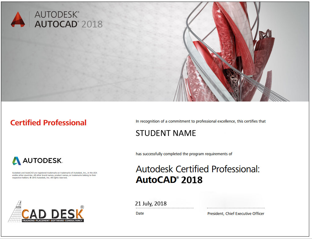
Assistance / Guidance for Licences Partner Dessault Certification
Assistance / Guidance for Licences Partner Certification
Assistance / Guidance for Licences Partner Certification
Have More Questions ? Frequently Asked Questions
No such prerequisite, however a basic knowledge to the subject is preferable.
Any person 10th Pass can pursue.
The training mode is LIVE Instructor led online training i.e by ZOOM, Skpye, Google MEET Etc
You have the facility to watch the recorded daily Missed lectures anytime.
Dont worry!! You will get recorded lectures on the mobile/web application, which you can see it later.
The batch start Every Weeks Monday
You can select the preferred start date & Time at the time of registration.
Special Batch / Weekend Batch Customized Training Available.
The average lecture duration shall be average 1 hour LIVE +QA
Extra 1 hour for practice & assignments at home is good.
There will be doubts QA and session everyday During LIVE Training .
You can share yours Doubts Share Screen to Trainer 1 to 1 Basis.
You Can get Training Material, Ebooks Assignments Access through Link during Training, Login Access , Gdrive etc
Once Enrolled you Cannot Cancel, However you can reschedule or Transfer the courses to Other Candidate or Other Softwares Training.
You may Join Other Live Batch ,Next Live Batch Adjustment with Pune Class room Batch & Recording also Available . Request to mail to [email protected] & whatsapp +91-8793166470
On registration we will send the link of the official software website link and you can download the trial software from there.
You Can join live classes through Smartphone or watch recorded videos through Phone anytime anywhere
However, you require Laptop or desktop for the practice and assignments.
You Can attend , Get Also Recording & can again practise with recordings and system -PC /Laptop once its available to you.
The certificate shall be provided in digital form ( E-Certificate ISO 9001:2015 with QR code once you complete the training .
The physical certificate you can take Color printout & laminate with less than Rs 50/- anywhere
Most industries/MNC and Universities/college recognise its certificate.
As off now there is no such authorising body in India for short term online courses so it all works on the virtue of reputation.
We do Provide free 100% Placements Assistance since already we are into placements since 10+ yrs.
100% Job Gurantee Even IIT & IIM also does not provide.
We don’t want to Give false promises …Covid19 taught us there is no guarantee of anyjob and no guarantee of any market conditions .
Offline doubt revision through any of Pune centers in India.
FREE Online rejoining Next Live Batch
Recording Acees Liftime
Placements Assistance